


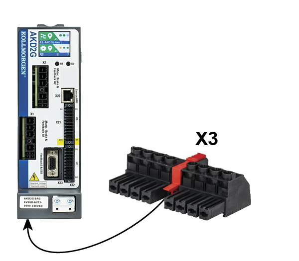
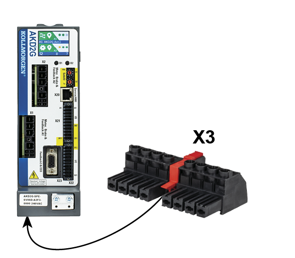
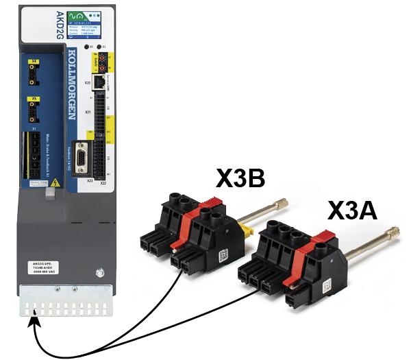
Mains power supply connector X3/X3A
Drives in the AKD2G series can be supplied as follows:
AKD2G-Sxx-6V
- 1, 2 or 3 phase industrial AC supply networks (TN-S or TT, see KDN): Single axis variants (S)
- DC supply networks: Single axis variants (S)
AKD2G-Sxx-7V
- 3 phase industrial AC supply networks (TN-S or TT, see KDN): Mains supply data, 3 phase AC, type AKD2G-Sxx- (D)
- DC supply networks: Mains supply data, DC, type AKD2G-Sxx- (D)
For connection to corner grounded delta supply networks contact Kollmorgen customer support.
Periodic overvoltages between phases (L1, L2, L3) and the PE/housing of the drive must not exceed 1,000V peak. In accordance with IEC 61800, voltage spikes (< 50 µs) between phases must not exceed 1,000V. Voltage spikes (< 50 µs) between a phase and the PE/housing must not exceed 2,000V.
|
|
|

|
|
Pin |
Label |
Signal |
1~ Supply |
2~Supply |
3~ Supply |
DC Supply |
|---|---|---|---|---|---|---|
|
1 |
PE |
PE |
Protective earth |
Protective earth |
Protective earth |
Protective earth |
|
2 |
L1 |
L1 |
Phase L1 |
Phase L1 |
Phase L1 |
+ DC |
|
3 |
L2 |
L2 |
n.c. |
n.c. |
Phase L2 |
n.c. |
|
4 |
L4 |
L3 |
Neutral N |
Phase L2 |
Phase L3 |
- DC |
For DC supply: observe notes DC supply (all AKD2G-Sxx-).
Wiring examples mains power supply
One phase AC mains (AKD2G-Sxx-6V)
- Directly to one phase supply network with neutral line.
- Activate single phase supply (VBUS.THREEPHASE = 0).
- Set VBUS.ACNOMINAL to desired nominal AC line voltage for lines other than nominal rated VAC.
- For complete information refer to WorkBench online help, AKD2G-S User Manual, section Power Setting.
- AC line filtering to be provided by the user. Use filter type FN2090, refer to the Accessories Manual for more information. Use shielded cable between filter and drive.

Two phases AC mains (AKD2G-Sxx-6V)
- Directly to two-phase supply network without neutral line.
- Activate single phase supply (VBUS.THREEPHASE = 0).
- Set VBUS.ACNOMINAL to desired nominal AC line voltage for lines other than nominal rated VAC.
- For complete information refer to WorkBench online help, AKD2G-S User Manual, section Power Setting.
- AC line filtering to be provided by the user. Use filter type FN2090, refer to the Accessories Manual for more information. Use shielded cable between filter and drive.

Three phases AC mains (all AKD2G-Sxx-)
- Directly to 3-phase supply network.
- Activate 3-phase supply (VBUS.THREEPHASE = 1).
- Set VBUS.ACNOMINAL to desired nominal AC line voltage for lines other than nominal rated VAC.
- For complete information refer to WorkBench online help, AKD2G-S User Manual, section Power Setting.
- AC line filtering to be provided by the user. Refer to the Accessories Manual for more filter description. Use shielded cable between filter and drive.
- AKD2G-Sxx-6V:
Motor cable < 10 m: use filter FN 3288 in industrial environment, category C2.
Motor cable ≥ 10 m: use filter FN 3288 in industrial environment, category C3. - AKD2G-Sxx-7V up to 12 Amps:
Motor cable < 10 m: no filter, in industrial environment, category C3.
Motor cable < 10 m: use filter FN 3288 in industrial environment, category C2.
Motor cable ≥ 10 m: use filter FN 3288 in industrial environment, category C3. - AKD2G-Sxx-7V 24:
Motor cable < 10 m: no filter, in industrial environment, category C2.
Motor cable ≥ 10 m: no filter, in industrial environment, category C3.
Motor cable ≥ 10 m: use filter FN 3288 in industrial environment, category C2.

- Activate DC supply (VBUS.DCOPERATION = 1) and set VBUS.DCNOMINAL.
- Any DC supply filtering for AKD2G-Sxx-6V to be provided by the user.
DC Supply to mains lines R/T (L1/L3)
DC power source is connected to the drive AC line inputs. This wiring provides soft start of the energy storage capacitors inside the drive and the AC rectifier diodes prevents motor regeneration energy from returning to the dc power source. That is, by powering the drive from the AC line input connections, the drive’s energy absorption and energy dissipation mechanisms can work normally.

DC Supply to DC Bus lines X3/7-8
|
|
When wiring DC power supply to the drive DC Bus terminals X3/X3B pins 7 and 8, the user is responsible for current and power management using additional external devices. For more information refer to KDN (AKD2G Low Voltage DC Operation). User responsibility:
|


Fusing
|
Fuse types |
Description |
|---|---|
|
US fuses |
Alternate fuses and breakers to Class J must have similar or better Ip and I²T performance per UL 508A SB4.2 at max. 10 kA SCCR rating. |
|
EU fuses |
|
|
Semiconductor |
|
|
Fuse holders |
Use finger-safe fuse holders according to EN 60529 in combination with the standard fuse blocks. |
|
Automatic circuit breakers |
|
|
Group installation fusing |
|
AC supply, single drives, line fusing

- F1, F2, F3: depends on sum of application's required input currents and cabinet requirements.
- Filters for special EMC requirements only (see "Conformance with EU").
- FN1, FN2, FN3 maximum rating: 30 A.
- FN1, FN2, FN3 recommended rating see table below:
|
Drive |
FN1, FN2, FN3: Ampere rating |
Example class J |
Example class J |
|---|---|---|---|
|
AKD2G-Sxx-6V03S |
10 A (Time-Delay) |
LPJ10SP, DFJ10 |
AJT10, HSJ10 |
|
AKD2G-Sxx-6V06S |
10 A (Time-Delay) |
LPJ10SP, DFJ10 |
AJT10, HSJ10 |
|
AKD2G-Sxx-6V12S |
15 A (Time-Delay) |
LPJ15SP, DFJ15 |
AJT15, HSJ15 |
|
AKD2G-Sxx-7V03S |
10 A (Time-Delay) |
LPJ-10SP, DFJ-10 |
AJT10, HSJ10 |
|
AKD2G-Sxx-7V06S |
10 A (Time-Delay) |
LPJ-10SP, DFJ-10 |
AJT10, HSJ10 |
|
AKD2G-Sxx-7V12S |
15 A (Time-Delay) |
LPJ-15SP, DFJ-15 |
AJT15, HSJ15 |
|
AKD2G-Sxx-7V24S |
25 A (Time-Delay) |
LPJ-25SP, DFJ-25 |
AJT25, HSJ25 |
|
Drive |
FN1, FN2, FN3: Ampere rating |
Semi-conductor |
Semi-conductor |
|---|---|---|---|
|
AKD2G-Sxx-6V03S |
10 A |
FWP-10G14F |
FR14GR69V10 |
|
AKD2G-Sxx-6V06S |
10 A |
FWP-10G14F |
FR14GR69V10 |
|
AKD2G-Sxx-6V12S |
15 A |
FWP-16G14F |
FR14GR69V16 |
|
AKD2G-Sxx-7V03S |
10 A |
FWP-10G14F |
FR14GR69V10 |
|
AKD2G-Sxx-7V06S |
10 A |
FWP-10G14F |
FR14GR69V10 |
|
AKD2G-Sxx-7V12S |
15 A |
FWP-16G14F |
FR14GR69V16 |
|
AKD2G-Sxx-7V24S |
32 A |
FWP-32G14F |
FR14GR69V32 |
AC supply, group of drives, line fusing

- F1, F2, F3: depends on sum of application's required input currents and cabinet requirements.
- Filters for special EMC requirements only (see "Conformance with EU").
- FN1, FN2, FN3 maximum rating: fuse size for group installation is limited to 30 A max. and 32 A max. for Semiconductor fuses.
- FN1, FN2, FN3 rating should be 1.25 * sum current.
|
Group sum current |
FN1, FN2, FN3: |
Eaton Bussmann |
Mersen |
|---|---|---|---|
|
6 A to 30 A |
30 A (Time-Delay) |
Example class J
|
Example class J
|
|
32 A |
Semiconductor
|
Semiconductor
|
|
|
The sum of the AC input currents (A1...n) is less than 30 A (32 A when semiconductor fuses are used). Additionally, the sum of the axes currents (I1...n) in parallel DC bus groupings must be less than 48 A. The maximum number of axes is limited to 8 drive enclosures per group installation. |
|
|
|


AC supply, single drives, automatic circuit breakers

- F1, F2, F3: depends on the sum of application's required input currents and cabinet requirements.
- Filters for special EMC requirements only (see "Conformance with EU").
- FN maximum rating: 30 A
- FN recommended rating and regional approvals see table below:
|
Drive Model |
Ampere |
SCCR |
Example ABB |
|---|---|---|---|
|
AKD2G-Sxx-6V |
15 A |
10 kA |
SU203M-K15 |
|
AKD2G-Sxx-7V |
15 A |
10 kA |
SU203M-K15 |
|
AKD2G-Sxx-7V24x |
30 A |
10 kA |
SU203M-K30 |
AC supply, group of drives, automatic circuit breakers

- F1, F2, F3: depends on sum of application's required input currents and cabinet requirements.
- Filters for special EMC requirements only (see "Conformance with EU").
- FN maximum rating: circuit breaker size for group installation is limited to 30 A max.
- FN rating should be 1.25 * sum current.
- FN recommended rating and regional approvals see table below:
|
Group sum current |
Ampere |
SCCR |
Example UL |
|---|---|---|---|
|
AKD2G-Sxx-6V |
|||
|
6 A to 9 A |
15 A |
10 kA |
SU203M-K15 |
|
12 A to 15 A |
20 A |
10 kA |
SU203M-K20 |
|
18 A to 24 A |
30 A |
10 kA |
SU203M-K30 |
|
27 A to 36 A |
30 A |
10 kA |
SU203M-K30 |
|
AKD2G-Sxx-7V |
|||
|
6 A to 9 A |
15 A |
10 kA |
SU203M-K15 |
|
12 A to 15 A |
20 A |
10 kA |
SU203M-K20 |
|
18 A to 24 A |
30 A |
10 kA |
SU203M-K30 |
|
27 A to 36 A |
30 A |
10 kA |
SU203M-K30 |
DC supply, single drives, line fusing

- F1, F2, F3: depends on sum of application's required input currents and cabinet requirements.
- Filters for special EMC requirements only (see "Conformance with EU").
- FN1, FN2 maximum rating 30 A
- FN1, FN2 recommended rating see table below:
|
Drive Model |
Ampere rating |
Example |
Example Mersen |
|---|---|---|---|
|
AKD2G-Sxx-6V03S |
10 A (Time-Delay) |
DFJ-10 |
HP6M10 |
|
AKD2G-Sxx-6V06S |
15 A (Time-Delay) |
DFJ-15 |
HP6M15 |
|
AKD2G-Sxx-6V12S |
15 A (Time-Delay) |
DFJ-15 |
HP6M15 |
|
AKD2G-Sxx-7V03S |
10 A (Time-Delay) |
FWP-10B |
HP10M10 |
|
AKD2G-Sxx-7V06S |
10 A (Time-Delay) |
FWP-10B |
HP10M10 |
|
AKD2G-Sxx-7V12S |
15 A (Time-Delay) |
FWP-15B |
HP10M15 |
|
AKD2G-Sxx-7V24S |
25 A (Time-Delay) |
FWP-25B |
HP10M25 |